
Triac is an important member of the thyristor family. It is an AC-controlled device because it is a bidirectional device that can pass current in both forward and reverse directions. A trial is equivalent to two back-to-back SCRs connected to the gate terminals.
TRIAC stands for TRIode AC Switch. TRI means the device has three terminals and AC means it can control AC power or pass AC power bi-directionally. A trial has three terminals, main terminal 1 (MT1), main terminal 2 (MT2), and gate (G). Current flows from MT1 to MT2 when MT1 is forward-biased with respect to MT2. Similarly, if MT2 is forward-biased with respect to MT1, the current will flow from MT2 to MT1.

Construction of TRIAC

A Triac is a semiconductor device with 5 layers and 3 terminals. The terminals are marked as MT1, MT2 as an anode, and cathode terminals for SCR. And the gate is represented by G, just like the thyristor. The gate terminal is connected to both the N4 and P2 regions by metal contacts and is near the MT1 terminal.
Terminal MT1 is connected to both N2 and P2 regions, and MT2 is connected to both N3 and P1 regions. The terminals MT1 and MT2, which are connected to both the P and N regions of the device, therefore determine, and the polarity of the voltage applied between these two terminals determines the current flowing through the layers of the device.
With the gate open, MT2 is positive with respect to MT1 for forward-biased triac. Therefore, the traic operates in forward blocking mode until the voltage across the triac drops below the forward break-over voltage. Similarly, for a reverse-biased Triac, MT2 will be negative with respect to MT1 whose gate is open.
The device operates in reverse blocking mode until the voltage across the triac drops below the reverse break-over voltage. The trace can be made conductive by a positive or negative voltage at the gate connection.
Symbol of TRIAC
A triac can be formed by connecting two equivalent SCRs in anti-parallel and connecting the gates of the two SCRs to form a single gate.

Working of TRIAC
Being a bidirectional device, you can connect various combinations of negative and positive voltages to the TRIAC terminals. The four possible electrode potential combinations that cause the triac to operate in four different quadrants or modes of operation are given as
- MT2 and the gate polarity is positive with respect to MT1
- MT2 and the gate polarity is negative with respect to MT1
- MT2 is positive but gate polarity is negative with respect to MT1
- MT2 is negative but gate polarity is positive with respect to MT1

In general, the latching current is higher in the 2nd quadrant or mode and the gate trigger current is higher in the 4th mode for each TRIAC compared to the other modes.
Most applications use negative trigger circuits. In other words, quadrants 2 and 3 are used for reliable triggering in bi-directional control and where gate sensitivity is important. When Mode 1 and Mode 4 are commonly used, they have the highest gate sensitivity.
Mode 1: MT2 is Positive, Positive Gate Current

When the gate terminal is pulled positive with respect to MT1, the gate current flows through the P2 and N2 junctions. When this current flows, the P2 layer is flooded with electrons, and these electrons diffuse further to the edge of the J2 (or P2-N1) junction.
These electrons collected by the N1 layer accumulate a space charge on the N1 layer. Therefore, more holes from the P1 region are diffused into the N1 region to neutralize the negative space charge. These holes reach the J2 junction and create a positive space charge in the P2 region, injecting more electrons from N2 to P2.
This results in positive regeneration and eventually, the main current flows from MT2 to MT1 through region P1-N1 – P2 – N2.
Mode 2: MT2 is Negative, Negative Gate Current

In this mode, N4 acts as a remote gate, injecting electrons into the P2 region. The external gate current forward biases the P2-N4 junction. Electrons from the N4 region are collected by the P2-N1 junction, increasing the current at the P1-N1 junction. Therefore, the P2-N1-P1-N3 structure turns ON due to regenerative operation. This mode makes the triac more sensitive than the positive gate current in Mode 3.
From the discussion above, modes 2 and 3 are less sensitive configurations that require more gate currents to trigger the TRIAC, while modes 1 and 4 are more common triggering modes for more sensitive TRIACs. and conclude. In practice, the more sensitive mode is chosen so that the polarity of the gate matches the polarity of terminal MT2.
Mode 3: MT2 is Positive, Negative Gate Current

If MT2 is positive with respect to MT1 and the gate is negative, the gate current will flow through the P2-N4 junction. This gate current forward biases the P2-N4 junction of the auxiliary structure P1-N1-P2-N4. This causes the triac to first conduct through the P1-N1-P2-N4 layer.
This further increases the potential between P2-N2 toward MT2. This causes the current to increase in the P2 layer from left to right, forward biasing the P2-N2 junction. Then the main structure P1-N1-P2-N2 begins to lead.
The first routed auxiliary structure P1-N1-P2-N4 is considered the pilot SCR and the later routed structure P1-N1-P2-N2 is considered the main SCR. Therefore, the pilot SCR’s anode current acts as the gate current to the main SCR. This mode has less sensitivity to gate current, so more gate current is required to turn on the triac.
Mode 4: MT2 is Negative, Positive Gate Current

In this mode MT2 is negative with respect to MT1 and the device is turned on by applying a positive voltage between the gate and the MT1 terminal. Turn-on is initiated by N2 acting as a remote control for the gate, the structure being a turn-on triac P2-N1-P1-N3.
An external gate current forward biases the P2-N2 junction. The N2 layer injects electrons into the P2 layer and is collected by the P2-N1 junction. This will increase the current through the P2-N1 junction. Five Holes injected from layer P2 diffuse through the N1 region. This causes a positive space charge to build up in the P region.
Therefore, more electrons are diffused from N3 to P1 to neutralize the positive space charge. These electrons, therefore, reach the J2 junction and generate a negative space charge in the N1 region, resulting in more holes injected from P2 into the N1 region. This regeneration process continues until the P2-N1-P1-N3 structure turns on the triac and conducts the external current.
The TRIAC is turned on by the remote gate N2, so the device is less sensitive to positive gate currents in this mode.
V-I Characteristics of TRIAC
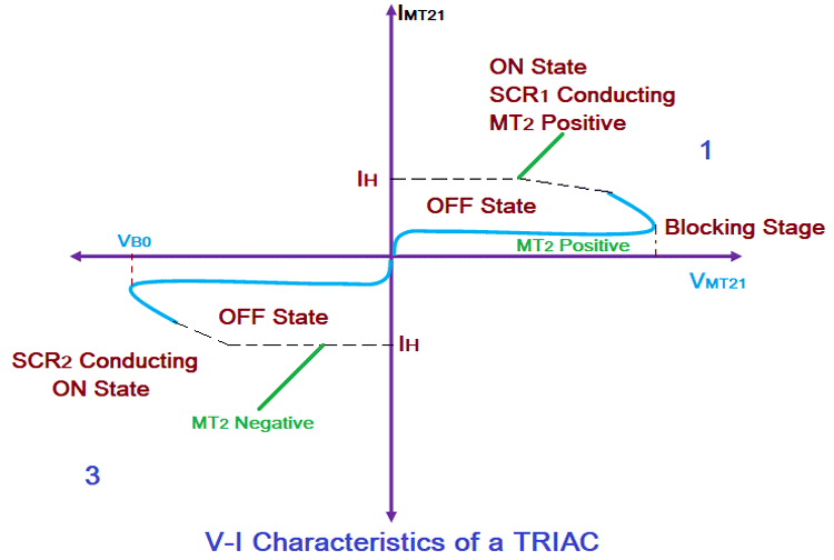
A TRIAC function is like two thyristors connected in anti-parallel, so the VI characteristics of a TRIAC in the first and third quadrants are similar to those of a thyristor. If terminal MT2 is positive to terminal MT1, the triac is said to be in forward blocking mode.
If the voltage across the device is less than the break-over voltage, a small amount of leakage current will flow through the device. When the break-over voltage of the device is reached, the TRIAC turns on as shown in the figure below.
However, the TRIAC can also be turned on below VBO by applying a gate pulse, so the current through the device must be greater than the TRIAC’s holding current.
Similarly, when terminal MT2 becomes negative with respect to MT1, the triac goes into reverse blocking mode. A small leakage current flows through the device until it is triggered by a break-over voltage or gate trigger method. A positive or negative pulse to the gate will therefore trigger the triac in either direction.
The supply voltage at which the TRIAC starts conducting depends on the gate current. The higher the gate current, the lower the supply voltage at which the triac turns on. Mode 1 triggering is used in the 1st quadrant and Mode 3 triggering is used in the 3rd quadrant.
Due to the internal structure of TRIACs, the actual values of latch current, gate trigger current, and holding current may vary slightly depending on the operating mode. The trace rating is therefore significantly lower than the thyristor rating.
Applications of TRIAC
- AC power controllers
- High Power Switch
- Phase Control