
A clamper circuit, also called a clamping circuit, is an electronic circuit that shifts the DC level of a signal without changing the shape of the waveform. It shifts the entire signal up or down by a reference level.
Unlike clipper circuits, it does not alter or distort the shape of the waveform. Simply add or subtract a DC level from the waveform to shift it above or below the 0V reference line.
Working of Clamper
The operation of the clamper circuit depends on changing in the time constant of the capacitor. This change is a result of the current path change in the diode as the polarity of the input signal changes.
where is the magnitude of the time constant
τ = RC
It is chosen large enough so that the voltage across the capacitor does not discharge during the reverse period of the diode. However, such discharge occurs only when the load resistance is very large. This increases the time it takes for the capacitor to discharge. Conversely, a smaller value capacitor is chosen so that it charges quickly when the diode conducts.
Types of Clamper
- Unbiased Clampers
- Biased Clampers
Unbiased Clampers
A clamper is said to be an unbiased clamper if it does not have a DC voltage source (bias) in series with the diode. It mainly consists of three components: diodes, resistors and capacitors. You can clamp the input signal on the positive or negative side of the amplitude axis based on the diode position.
An unbiased clamper also consist of two types which are given below:
- Positive Clamper
- Negative Clamper
Positive Clamper
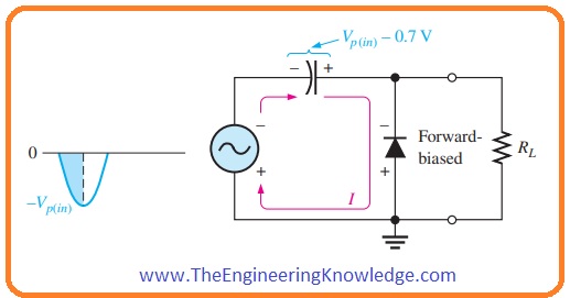
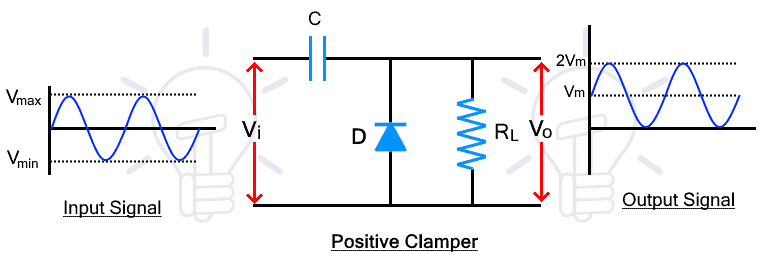
A positive clamper circuit shifts the input waveform above the 0V reference line. Here is the schematic for the positive clamper circuit.
During the positive half-cycle, the diode is reverse-biased, so the input signal appears unchanged at the output. At this point the capacitor is not charged and is not clamped. Therefore the output is not considered in this half cycle.
During the next negative half cycle, the diode becomes forward biased and begins to conduct. During this half-cycle, the capacitor charges in reverse polarity to the peak input voltage VM.
During the next positive half cycle, the diode becomes reverse biased and does not conduct. This causes the capacitor to start discharging. The capacitor discharge is added to the input signal and appears at the output as the sum of both voltages, reaching up to 2 VM. This shifts the signal level above the 0V line.
Negative Clamper
A negative clamp shifts the entire input waveform down. This is the schematic of the negative clamp circuit.
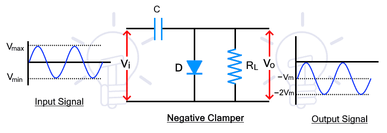
During the positive half cycle the diode is forward biased. Therefore, the capacitor conducts in reverse polarity and charges to the peak input voltage -VM. There is no output during this half cycle.
During the negative half cycle the diode is reverse biased and does not conduct. Therefore the capacitor is discharged and added to the input waveform. Adding both voltages shifts the overall waveform further to -2VM. This shifts the input signal down.
Biased Clamper
If the DC shift obtained at the output by using unbiased clampers is not sufficient, then a suitable dc voltage source (bias) should be placed in series with the diode. This circuit is then known as a bias clamper. Based on the position of the diode and the polarity of the DC voltage source (bias), the input signal can be clamped on the positive or negative side of the amplitude axis.
Two types of Biasing which is given below:
- Positive Clamper Biasing
- Negative Clamper Biasing
Positive Clamper Biasing
The positive clamper can be biased with another voltage source to further shift the input signal waveform. The biasing can be either positive or negative voltage. Simply put, a positive biasing shifts the waveform further up, and a negative biasing lowers it by the biasing voltage amount.
Positive Clamper with Positive Bias
During positive biasing, a positive voltage source is added in series with the diode as shown in the figure below.
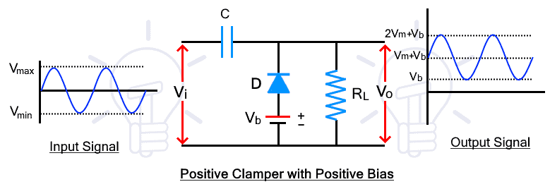
During the positive half-cycle, the diode is reverse biased with respect to the input signal, but forward biased with respect to the battery voltage. So the diode will conduct until the input voltage exceeds the battery. During conduction the capacitor is charged with the battery voltage VB. When the input voltage is exceeded, the diode stops conducting.
During the negative half-cycle, the diode is forward biased with respect to both the input voltage and the battery voltage. So the diode conducts and charges the capacitor with both the input voltage and the battery voltage VM + VB. On the next positive half cycle, the capacitor is discharged and affects the input signal waveform as described in the positive clamper circuit.
Positive Clamper with Negative Bias
A negative biased positive clamper behaves the same as a positive biased clamper, but the waveform is shifted down by the amount of the battery voltage VB.
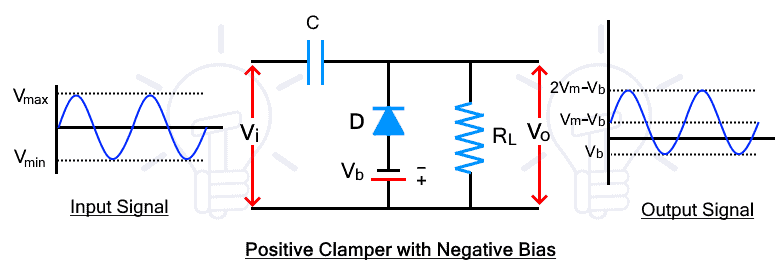
During the positive half cycle the diode is reverse biased by both the input voltage and the battery voltage. The diode will not conduct and the capacitor will not charge.
During the negative half cycle, the diode is forward biased with respect to the input voltage, but reverse biased with respect to the battery voltage VB. So the diode will not conduct unless the input voltage exceeds the battery voltage. When the diode conducts, the capacitor is charged. This will drop the capacitor charging voltage to his VM-VB.
On the next positive cycle, the diode does not conduct, so the capacitor discharges and the waveform shifts up by VM – VB (capacitor voltage). Bias shifts the waveform down by the amount of his VB in the positive clamp.
Negative Clamper Biasing
The positive and negative bias of the negative clamper shifts the waveform further up and down.
Negative Clamper with Positive Bias
The positive bias of the negative clamper adds a positive or upward shift to the negative clamped waveform by the amount of biasing voltage. A positive bias shifts the waveform to positive levels.
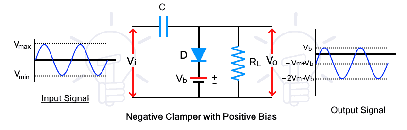
During the positive half-cycle, the diode is forward biased with respect to the input voltage, but reverse biased with respect to the battery voltage. When the input voltage exceeds the battery, the diode conducts and charges the capacitor. Therefore, the charge on the capacitor is reduced by VB and the voltage on the capacitor is -VM + VB.
During the negative half cycle, the diode does not conduct and the capacitor discharges. The sum of the input voltage and capacitor appears at the output, shifting VB upward as shown in the figure above.
Negative Clamper with Negative Bias
The negative bias of the negative clamper shifts the input signal waveform further down.
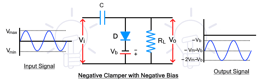
During the positive half-cycle, the diode is forward biased for both the input signal and the battery voltage. The diode then conducts and the capacitor is charged with the sum of both voltages.
During the negative half cycle, the diode is reverse biased with respect to the input voltage, but conducts with respect to the battery voltage. When the input voltage exceeds the battery, the diode blocks the signal, including the capacitor discharge voltage, appearing at the output. As a result, the waveform shifts further down as shown in above fig.
Applications of Clamper Circuit
- Voltage multiplier
- Improving the reverse recovery time
- Removing the distortion in the signal
- Test equipment.