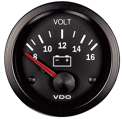
Introduction
A voltmeter is an essential tool for measuring voltage levels in electronic circuits. By using Zener diodes and a few additional components, you can build a simple voltmeter circuit. In this article, we will guide you through the process of building a voltmeter circuit with Zener diodes, explaining the required components, the working principles, and the applications of this circuit.

Required Components
Before you start building your voltmeter circuit, make sure you have the following components:
- 1N4739 9.1V Zener Diode
- 1N4733 5.1V Zener Diode
- 1N4741 12V Zener Diode
- 1N4728 3.3V Zener Diode
- 4 470Ω resistors
- 4 LEDs
Circuit Diagram

The breadboard schematic of the above circuit is shown below.

Working of the Voltmeter Circuit
The voltmeter circuit with Zener diodes works based on the principle of comparing the input voltage with a known reference voltage. The Zener diode, operated in reverse breakdown mode, provides a stable reference voltage. The voltage across the Zener diode remains constant, even if the input voltage varies.
The voltage drop across the current-limiting resistor produces a proportional voltage that is fed into the non-inverting input of the op-amp. The potentiometer allows you to calibrate the voltmeter to match the reference voltage.
The op-amp amplifies the voltage difference between the input and reference voltages. The amplified voltage is then displayed on the analog meter or display, providing the voltage measurement.
Circuit Design and Assembly
To build a voltmeter circuit with Zener diodes, follow these steps:
- Choose the appropriate Zener diode with a breakdown voltage that matches the range of voltages you want to measure.
- Determine the value of the series current-limiting resistor based on the desired maximum current through the Zener diode.
- Connect the Zener diode in reverse bias across the power supply.
- Connect the series current-limiting resistor in series with the Zener diode.
- Connect the other end of the resistor to the non-inverting input of the op-amp.
- Connect the inverting input of the op-amp to the reference voltage (e.g., ground).
- Connect the potentiometer in parallel with the Zener diode and resistor. This allows you to calibrate the voltmeter for accurate readings.
- Connect the output of the op-amp to the analog display.
Ensure that the polarities of the Zener diode, resistors, op-amp, and power supply are properly aligned according to the circuit diagram.
Applications of Voltmeter Circuits
Voltmeter circuits find applications in various electronic systems. Some common uses include:
Electronic Testing and Measurement
Voltmeter circuits are used for measuring voltages in electronic circuits and components during testing and troubleshooting.
Power Supply Monitoring
They can monitor the voltage output of power supplies to ensure they are operating within the desired range.
Battery Voltage Measurement
Voltmeter circuits can measure the voltage level of batteries to determine their state of charge.
Circuit Calibration
They can be used for calibrating other measuring instruments or circuits by comparing their readings to the voltmeter’s known reference voltage.

