
A clipper is a device that removes the positive half (top half), negative half (bottom half), or both positive and negative halves of an AC input signal. In other words, a clipper is a device that limits the positive or negative amplitude, or both positive and negative amplitude, of an AC input signal.
A clipper circuit cuts or removes a portion of an AC signal without distorting or altering the rest of the waveform. It limits the voltage from rising above or below a certain point. Therefore, it is also used for protection against over voltages. Clipper circuits are also known as clippers, clipping circuits, voltage limiters or slicers, etc.
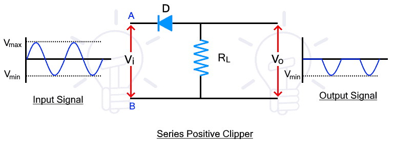
Clipper circuits can be either series clippers or shunt clippers, and both types can be used to clip half or part of a waveform. The change in waveform shape depends on the type of clipper circuit.
A clipping circuit consists of linear elements such as resistors and nonlinear elements such as diodes and transistors, but does not contain energy storage elements such as capacitors.
Working Of Clipper
Clipper circuits can be designed using diodes and resistors. The simplest form of clipper circuit is a half-wave rectifier, which is easily designed using diodes and resistors. When an AC signal is applied to a particular rectifier, the signal sweeps through the positive half-cycles and discards the rectifier’s negative half-cycles.
By reversing the direction of the diode, we have the opportunity to pass the negative half cycle and discard or rejects the positive half cycle. So, depending on one of the portions of the waveform is clipped.

Types of Clipper
- Diode Clipper
- Zener diode Clipper
- Op-amp precision Clipper
Diode Clipper
A simple diode clipper can be created using a diode and a resistor. This removes the positive or negative half of the waveform, depending on the direction the diode is connected. A simple circuit clips at zero voltage (more precisely, the small forward voltage of a forward-biased diode), but the clipping voltage can be set to any value by adding a reference voltage. Although the diagram shows a positive reference voltage, the reference can be positive or negative for both positive and negative clipping, for a total of four possible configurations.

Zener Diode Clipper
Two zener diodes can be used to cut off both halves of the input waveform. The Zener diodes are connected in reverse polarity as shown below.

During the positive half cycle, Zener diode ZD1 is reverse biased and Zener diode ZD2 is forward biased. First, diode ZD1 does not allow current. Hence the signal appears at the output. However, when the input voltage exceeds the Zener breakdown voltage, the Zener diode starts to conduct and the Zener voltage Vz1 of Zener diode ZD1 starts to appear at the output. Similarly, the negative half cycle clips the negative waveform after the Zener voltage of ZD2.
Op-amp Precision Clipper
If the value of the low-level signal clipping voltage is very small, the I-V curve of the diode may not be very sharp at the onset of clipping. A precision clipper can be created by placing a clipping device in the feedback circuit of an op amp, similar to a precision rectifier.
Applications of Clipper
- Signal receiving and signal transmitting devices
- Communication systems
- Over-voltage protection
- Voltage limiting
- Waveform modification